
LINKS TO FEATURED PAGES:
![]() TRIUMPH Contents
page > FAQ Contents > TR3
overheating
TRIUMPH Contents
page > FAQ Contents > TR3
overheating
|
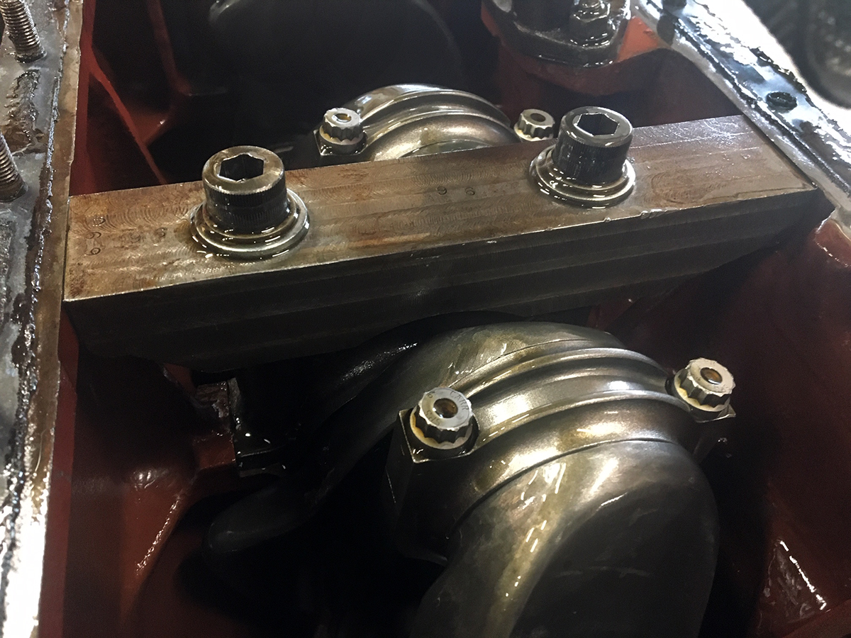
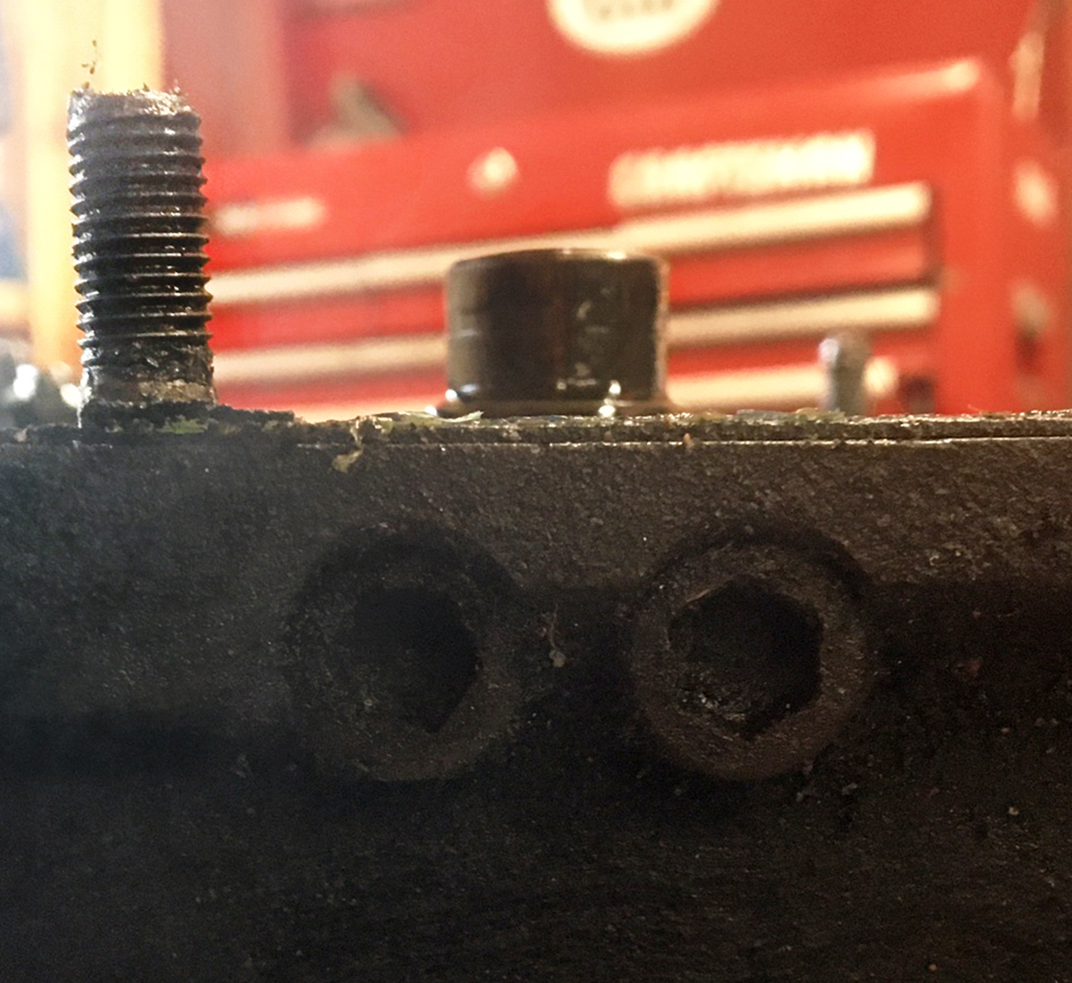
A summary based upon several FOT e-mail comments: Cranks have multiple harmonics, each successive one stronger than the last. Harmonics are generated by the crankshaft flexing during rotation. Changing the weight hanging off the end of a crank, the rotating weights of the pistons, rods, and flywheel will change the RPM where the harmonics occur, raising the RPM where the harmonics occur as rotating weights are lightened. The first harmonic is very mild and unnoticeable except for maybe fuel bowl frothing (more noticeable with the longer TR4 intake manifolds) at about 2800 RPM. The second is much stronger and comes in from about 5200 to 5600 RPM depending upon the individual engine. This harmonic flexes the crank at the flywheel end and tends to break the crank at the flywheel mounting flange if you spend much time at that RPM range. This is why the Triumph factory red lined the engine at 5000 RPM. Going to a lighter flywheel will raise the RPM where this second harmonic occurs. Nitriding a crankshaft will strengthen it making it less likely to break as will lightening the pistons and rods to reduce reciprocating weight. The TR3/4 engine does not come with a harmonic balancer. People who had access to the British Leyland crank harmonics test data sheets went through them to find a crank with the most similar harmonic data and had a harmonic dampener. One was found and that harmonic dampener can be fitted to the Triumph 3/4 engine. The harmonic dampener adds a weight at the front of the crankshaft to balance the weight of the flywheel and dampen the second harmonic mostly taming the second harmonic so as not to break the crankshaft. It takes up space where the stock mechanical fan is located and requires a change to a narrow belt pulley. The third harmonic occurs somewhere around the low mid 6000 RPM range, where street engines with 3/4 race cams shouldn't go but some race prepared engines often reach and exceed. This harmonic causes the crankshaft to bend at the middle and can damage crank journals as well as the crank. Spend much time in that RPM range without compensating for it and the engine will very likely come apart. Race engines that commonly reach 7000+ RPM strengthen the block and journal by adding a block strap across the main journal, bolting it to both sides of the block. Basically just strapping the journal down so the harmonic forces cannot bend the crankshaft. Some comments from FOT members: Back in 1980, Fred Baker won the run-offs at Road Atlanta in a Jag XKE. One thing that he said helped was making the flywheel and harmonic damper as close to the same weight as possible He used some big American car damper. They had trouble making maximum RPM and ran the engine on a dyno with a strobe light on the flywheel and noticed a severe flex to the crank. They increased the damper weight and the vibration was reduced giving close to 1,000 more RPM. The cranks "wiggle" at high RPM. Matching the weight at both ends reduced that. They did blow the engine the next week when giving writers a test ride. I used this theory on my TR4A using a factory crank that I modified and lightened, I used an ATI custom damper and a lightened aluminum flywheel (less than 18 lbs for flywheel, PP and disc) and was able to turn the engine to 7,300. I also used a custom 1/4" plate bolted to the oil pan rail and across to the center main caps. Maybe some one can get more info on this theory. Note this engine has lighter than stock pistons and connecting rods which is a big gain taking some of that reciprocating/ bending load off the mains. Barry Rosenberg I noticed the second harmonic on track at 5600 rpm because it foamed the fuel in the float bowl, not because I actually felt it. - Tony Drews On my street TR4A, the harmonics came in about 2800 RPM and again at 5600 RPM. It was an interesting sensation. Hard to describe I never noticed it in any of the race engines. Joe Alexander The third harmonic is reached around 6300 RPM or higher depending upon engine rotating weight modifications and is usually the most destructive harmonic. This harmonic bends the crankshaft at the middle usually, but not always around the mid distance crank. But can be around the 2nd crank journal in the 4 Cyl engine. You will see that a lot of people will fit billet, machined, large main bearing cap around mid-crank length as they have had issues with either bearing ‘wipe’ of broken cap bolts. They are trying to counteract the third harmonic by making the bearing journal stiffer. I run that setup, it was an uncle jack trick. Here's what he wrote about that (on my engine building tips page): "I also like to strap the center main to add rigidity to the bottom end. To do this, mill off the cast face of the main flush with the surfaces for the head bolts. Get a front strap for a Chevy 400 block. You must enlarge the holes in the strap and you must use longer bolts. Some builders feel that this is totally unnecessary, but since starting to do this, I have never had a main bearing deteriorate faster than a rod bearing, which is something that happens more frequently than you would expect." Tony Drews
Has anyone seen the need to add extra support to the center main on the TR wet sleeve engine? We have an engine that has a steel bridge cross-bolted underneath and supporting the center main cap. Is this needed? Just took 3 factory cranks to the machine shop and all three were bent about .002 in (.002 run out at center main when supported on first and last mains.) Two of these were raced, the third was removed from a tired street engine. note: None of these cranks came out of the engine with extra support at the center. Curious as to the need for the extra support. Thanks, Phil Gott 114 TR4A Phil, A few years ago we were running a 3/4 race TR-4A engine on the dyno. We ran it with H-6 carbs on a short manifold and HS-6 Carbs on a long manifold. With the H-6 carbs, the engine ran as we expected and would pull from about 2500 RPM up to about 6,500 RPM smoothly and evenly. peak power was at about 5,500 rpm. When we switched to the HS-6 carbs on the long manifold we found substantially more power and torque from 2,800 rpm on up the rev range, but at 5200 rpm the power died and the bsfc went all to hell. We determined that the fuel was foaming in the float bowls and making the fuel mixture go wild. We installed the MG_B style rubber mounts for the float bowls so that they were flexibly mounted, not solid as with the TR-4A setup, but that did not cure the issue. We then used weber 45dcoe soft mount kits to create a rubber cushion between the carb body and the inlet manifold. That cured the problem. The power then continued smoothly past the vibration period up to 6,000 RPM where it fell off because of the cam that was in the engine. Apparently the length of the long inlet manifold amplified the vibration frequency from the engine and caused the fuel mixture in the carb bowls and jet to foam, destroying the fuel mixture. Isolating the carb from the engine vibration cured the problem. Greg Solow
|
|

© 1997 - 2017 TeriAnn Wakeman. All rights reserved.